Low End Mac's Online Tech Journal
Life After the 400K Click of Death
- written 2001.10.08, last modified, 2001.11.17, edited for use on Low End Mac: 2006.05.18
This invaluable resource disappeared from the Web for a while. Thanks to A. Daniel King for permission to post it here on Low End Mac and to Hardy Menagh for recreating the photos that originally accompanied this article.
In my preceding article, Vintage Mac 400K Floppy Drive Repeating Click of Death, we learned how to get past the horrible "click, click, click" frequently found in these increasingly rare drives.
However, the previous article did not address a common problem collectors find after having repaired the "Click of Death". Frequently, the enthusiastic Mac user finds that his repaired drive is no longer stuck from fossilized lubricant, no longer clicking, and still not reading floppy disks either!
What is this common problem working with 400 KB disks, and how do I achieve "Life After the Click of Death"?
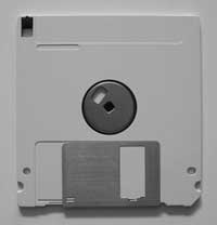
First, a note: We use 800 KB (or DD, double density) floppy disks in our 400K drives. Why? The 400K drive is single-sided. 800K drives simply use both sides. No problems should occur with 800 KB floppies, though using other density disks - 1.4 MB or higher - will result in unpredictable results. The physical difference between the two diskette types is shown in Figures 1 & 2.
Second, let's identify the problem. The older Macintosh, when connected to the 400K drive with an 800 KB floppy disk inserted, will try to read and write normally. The read-write mechanism makes typical sounds (no grinding to speak of): the disk whirrs, and regardless of what is actually on the floppy, the Mac lets you know that you should erase or eject the diskette. This process is repeatable and even fails with a known good 400 KB formatted floppy. Erasing the disk produces an operation failure message and probably destroys all the data on the disk. Bummer.
How Do I Fix It?
The problem can most commonly be traced to a single screw that adjusts the distance between the drive read/write head and the floppy disk.
The author assumes common sense, disconnected power, a static strip armband (if desired), several Phillips and flathead screwdrivers of varying small sizes, a handful of Q-tips, some fingernail polish (use your favorite color), some nail polish remover, and about an hour of your time. A pair of locking tweezers or forceps would also be nice.
The author claims no responsibility for any problems arising from this process - technical, personal, or otherwise.
 Figure
1: The Double-Density Floppy Disk (a.k.a. DD, 800 KB) viewed
from the back (left). Note the hole in the upper, left-hand corner
and the black tab just above it. Because we can see through the
hole, we know that this floppy disk is write-protected. We can
write to the disk by sliding the black tab into the down position.
Because there is no corresponding hole on the right-hand side, we
know that this is an 800 KB floppy.
Figure
1: The Double-Density Floppy Disk (a.k.a. DD, 800 KB) viewed
from the back (left). Note the hole in the upper, left-hand corner
and the black tab just above it. Because we can see through the
hole, we know that this floppy disk is write-protected. We can
write to the disk by sliding the black tab into the down position.
Because there is no corresponding hole on the right-hand side, we
know that this is an 800 KB floppy.
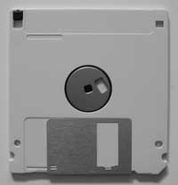 Figure 2: The High-Density Floppy Disk (a.k.a. HD,
1.4 MB) viewed from the back (right). Note the hole in the upper,
left-hand corner, the black tab just above it, and the hole in the
upper right-hand side. Because we can see through the left hole, we
know that this floppy disk is write-protected, as with the above
800 KB floppy. Because there is a hole on the right-hand side, we
know that this is a 1.4 MB floppy. Do not use this type of
disk with your 400K drive if you value your data.
Figure 2: The High-Density Floppy Disk (a.k.a. HD,
1.4 MB) viewed from the back (right). Note the hole in the upper,
left-hand corner, the black tab just above it, and the hole in the
upper right-hand side. Because we can see through the left hole, we
know that this floppy disk is write-protected, as with the above
800 KB floppy. Because there is a hole on the right-hand side, we
know that this is a 1.4 MB floppy. Do not use this type of
disk with your 400K drive if you value your data.
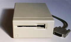
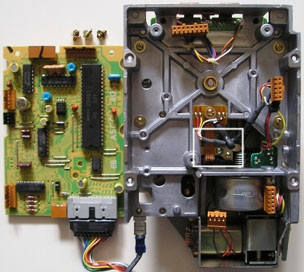 Figure 3: Underneath the
Drive. The diskette opening is toward the top.
Figure 3: Underneath the
Drive. The diskette opening is toward the top.
- I'll assume that you've already got the case off. In addition to the case, you will want to remove the three screws holding the main logic board to the drive chassis as well as the handful of connectors from the logic board to the drive chassis. The chassis wires and connectors should be relatively sturdy - unlike some we will see in a moment. I found that I did not need to disconnect the connectors at the back of the drive. This done, you should end up with something like Figure 3 (left).
- Within the white rectangle of Figure 3, you will see the general area of concentration. Close-up views follow in Figures 4, 5 & 6.
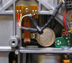 Figure 4: Screw with
Coin (right). This is given for scale.
Figure 4: Screw with
Coin (right). This is given for scale.
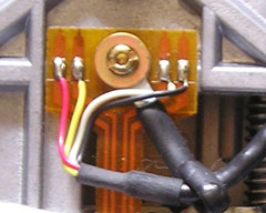 Figure 5: Close-up of
Wires (left). These are the wires to avoid moving, if
possible.
Figure 5: Close-up of
Wires (left). These are the wires to avoid moving, if
possible.
These wires are very delicate, and you should move them as little as possible. They are held in place by a flexible/bendable brace and a single screw. If you must move the wires, removing the screw is probably your best bet, but you may also bend the brace if desired.
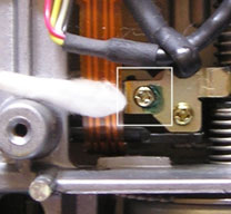 Figure 6: Close-up of
Screw (right). This is the adjustment screw.
Figure 6: Close-up of
Screw (right). This is the adjustment screw.
Given the warning in Figure 5, you still may have to move the wires. The screw we are looking for is directly underneath the delicate wires - as seen in the white box of Figure 6.
- Figure 6 shows the adjustment screw in question. If your drive is like mine, the screw is secured by some plastic- or paint-like material. Mechanical (and especially electromechanical) screws and fasteners are commonly held in place by similar material. You can probably turn the screw (and break the "paint") with brute force. However, this material may be removed with a Q-tip and some nail-polish remover. Be careful not to get the nail-polish remover on any other components. You'll want to remove the "paint" before continuing, because we will apply a near substitute - fingernail polish - to resecure the screw when done.
- You will need to do some adjustment of this screw to find out exactly where it needs to be. In my case, I turned the screw fully clockwise, achieving the maximum height of the read/write head. This was adequate for my purposes, and the drive was reading/writing beautifully!
- Once you have the correct placement of the drive head, use one or two drops of fingernail polish to secure the screw. Wait for the fingernail polish to dry before reassembling the unit.
That should do it!
Let me know how it goes....